
This article shows how to calculate the maximum bending moment at a fixed section of a simply supported beam subjected to three moving concentrated loads representing the axles of a vehicle, using the influence-line ordinates at the load positions.
1 Bending moment for an arbitrary vehicle position
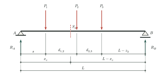
Consider a simply supported beam of span \(L>0\) subjected to three nonnegative, downward-moving concentrated loads \(P_1\), \(P_2\), and \(P_3\). The loads move together while maintaining the positive spacings \(d_{1,2}\) and \(d_{2,3}\) between them. Let \(s\) denote the reference position of the vehicle. The position \(z_1\) of the first load is taken to coincide with \(s\), so that \(z_1 = s\); the other positions \(z_2\) and \(z_3\) follow from the fixed spacings between loads.
\[\begin{equation} z_1(s)=s,\qquad z_2(s)=s+d_{1,2},\qquad z_3(s)=s+d_{1,2}+d_{2,3} \end{equation}\]
In the special case of equal load spacings, \(d_{1,2} = d_{2,3} = d\), the load positions as functions of the reference position \(s\) are:
\[\begin{equation} z_1(s) = s, \qquad z_2(s) = s + d, \qquad z_3(s) = s + 2d \end{equation}\]
The bending-moment influence line at a fixed section \(S_x\) located at \(x_c\), for a unit vertical load positioned at \(z\), including positions outside the beam span (\(z<0\) or \(z>L\)), is defined by:
\[\begin{equation} M_I(z)= \begin{cases} \dfrac{z(L-x_c)}{L}, & 0\le z\le x_c,\\[6pt] \dfrac{x_c(L-z)}{L}, & x_c<z\le L,\\[6pt] 0, & z\notin[0,L] \end{cases} \end{equation}\]
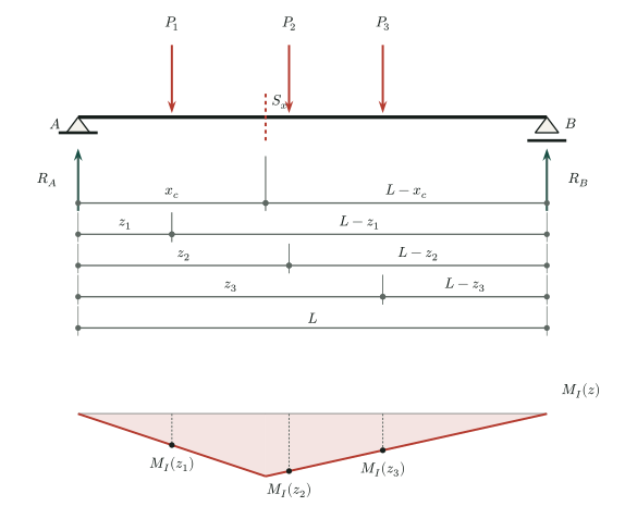
As shown previously, the bending moment at a fixed section is the sum of the products of the load magnitudes and the bending-moment influence-line ordinates at their respective positions:
\[\begin{equation} M(s) = P_1 M_I\big(z_1(s)\big) + P_2 M_I\big(z_2(s)\big) + P_3 M_I\big(z_3(s)\big) \end{equation}\]
In the special case where all three loads have the same magnitude \(P_m\), that is, \(P_1 = P_2 = P_3 = P_m\), the bending moment at the fixed section due to the three loads is:
\[\begin{equation} M(s) = P_m \big[ M_I\big(z_1(s)\big) + M_I\big(z_2(s)\big) + M_I\big(z_3(s)\big) \big] \end{equation}\]
Thus, the bending moment at any fixed section of the beam can be determined as the loads move along the span.
Finding the maximum bending moment, however, requires identifying the critical load positions. For statically determinate structures, influence lines are piecewise linear (that is, they consist of straight-line segments forming a polygonal function). Because a sum of piecewise-linear functions is also piecewise linear, the maximum bending moment occurs at a position where one of the concentrated loads coincides with a vertex of this polygonal function.
For bending moment in a simply supported beam, the influence line has two linear segments within the span, is zero at the supports, and has a vertex at the fixed section \(x_c\). Its zero extension beyond the span also introduces vertices at the supports. For nonnegative loads, however, a load entering or leaving the span produces a nonnegative jump in the slope of \(M(s)\) and does not create an isolated maximum. Thus, over the vehicle’s entire passage, at least one maximum occurs when a load is directly over the fixed section, that is, when \(z_i(s) = x_c\) for some \(i \in \{1,2,3\}\). A plateau of maximum values may include other positions.
Although the vehicle is represented by three moving loads traveling across the beam, it is important to consider not only when the vehicle is entirely on the beam (all three loads acting simultaneously), but also when only one or two loads are on the beam. All possible scenarios must therefore be considered to determine the maximum bending moment correctly at any section of the beam. These scenarios are:
Scenario 1 – Only one load is on the beam.
Scenario 2 – Two loads are on the beam.
Scenario 3 – All three loads are on the beam.
If \(L<d\), intervals with no loads on the beam also occur between the departure of one load and the arrival of the next. During these intervals, \(M(s)=0\), so they need not be included in the comparison of maxima. The following figures show candidate positions where a load is directly over the section, rather than every possible vehicle position.
2 Scenario 1 – Only one load is on the beam
From here on, assume equal loads of magnitude \(P_m\) and equal spacings \(d>0\), with \(0\le x_c\le L\). In this scenario, only one load is on the beam. If \(P_1\) is at the section, this requires \(x_c+d>L\); if \(P_3\) is at the section, it requires \(x_c-d<0\). Only \(P_2\) is on the span when \(x_c-d<0\) and \(x_c+d>L\). For an interior section, this can occur whenever \(L<2d\): if \(L\le d\), it holds at every interior section; if \(d<L<2d\), it requires \(L-d<x_c<d\).
The following cases are possible in this scenario:
Case 1.a – The position \(z_1\) of load \(P_1\) coincides with the section position \(x_c\). Loads \(P_2\) and \(P_3\) are outside the beam.
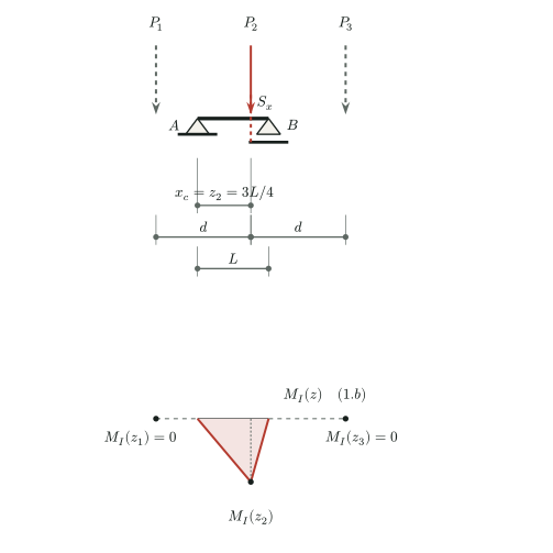
Case 1.b – The position \(z_2\) of load \(P_2\) coincides with the section position \(x_c\). Load \(P_1\) is to the left of the beam, and load \(P_3\) is to the right.
Case 1.c – The position \(z_3\) of load \(P_3\) coincides with the section position \(x_c\). Loads \(P_1\) and \(P_2\) are outside the beam.
2.1 Case 1.a – The position \(z_1\) of load \(P_1\) coincides with the section position \(x_c\)
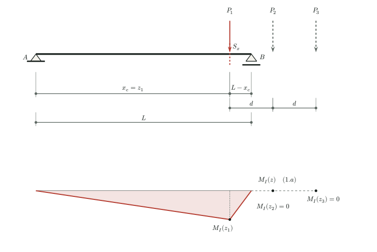
In this case:
\[\begin{equation} z_1(s) = s = x_c, \quad z_2(s) = s + d = x_c + d > L, \quad z_3(s) = s + 2d = x_c + 2d > L \end{equation}\]
2.2 Case 1.b – The position \(z_2\) of load \(P_2\) coincides with the section position \(x_c\)
The neighboring loads lie outside the span when \(P_2\) is at the section and \(x_c-d<0\), \(x_c+d>L\):
\[\begin{equation} s=x_c-d,\qquad z_1(s)=x_c-d<0,\qquad z_2(s)=x_c,\qquad z_3(s)=x_c+d>L. \end{equation}\]
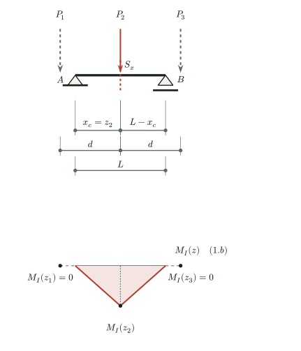
2.3 Case 1.c – The position \(z_3\) of load \(P_3\) coincides with the section position \(x_c\)
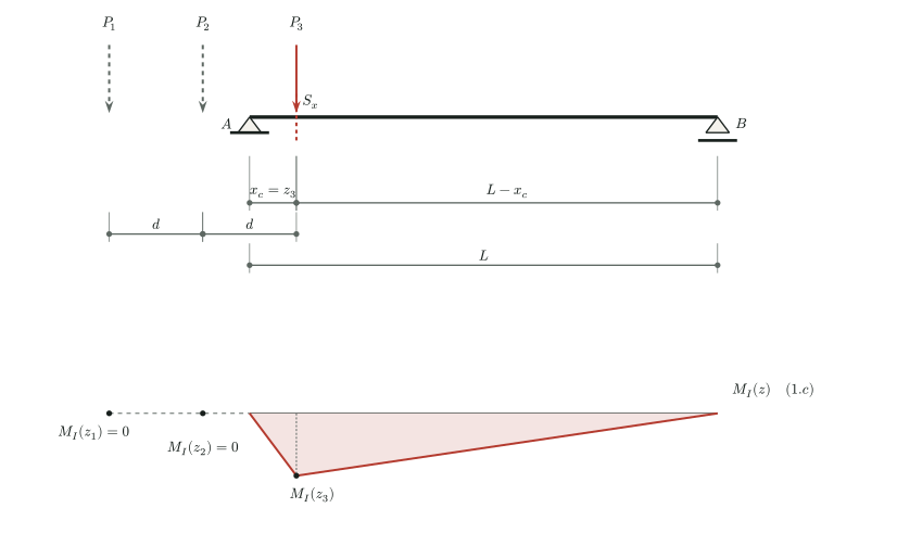
In this case:
\[\begin{equation} s=x_c-2d,\quad z_1(s)=s=x_c-2d<0,\quad z_2(s)=s+d=x_c-d<0,\quad z_3(s)=s+2d=x_c \end{equation}\]
In all three cases, 1.a, 1.b, and 1.c, let \(P_j\) be the only load on the span, directly over the section, so that \(z_j=x_c\) for \(j\in\{1,2,3\}\). For \(i\in\{1,2,3\}\), the influence-line ordinates are:
\[\begin{equation} M_I(z_i)= \begin{cases} \dfrac{x_c(L-x_c)}{L}, & i=j,\\[6pt] 0, & i\ne j. \end{cases} \end{equation}\]
Thus, because the loads have equal magnitudes, the bending moment at the section is the same in all three cases:
\[\begin{equation} M^{(1)}_{S_x}=P_m M_I(z_j)=\dfrac{P_m x_c(L-x_c)}{L},\qquad j\in\{1,2,3\}. \end{equation}\]
3 Scenario 2 – Only two loads are on the beam
In this scenario, only two consecutive loads are on the beam: because \(z_1<z_2<z_3\), \(P_1\) and \(P_3\) cannot both be on the span without \(P_2\). Case 2.a requires \(x_c+d\le L<x_c+2d\); Case 2.b requires \(0\le x_c-d\) and \(x_c+d>L\); Case 2.c requires \(x_c-2d<0\le x_c-d\); and Case 2.d requires \(x_c-d<0\) and \(x_c+d\le L\).
The following cases are possible in this scenario:
Case 2.a – The position \(z_1\) of load \(P_1\) coincides with the position \(x_c\) of the fixed section, and load \(P_2\) is also on the beam near the right support. Load \(P_3\) is outside the beam;
Case 2.b – Load \(P_2\) is at the section, and \(P_1\) is also on the beam; \(P_3\) is outside the beam to the right;
Case 2.c – The position \(z_3\) of load \(P_3\) coincides with the position \(x_c\) of the fixed section, and load \(P_2\) is also on the beam near the left support. Load \(P_1\) is outside the beam;
Case 2.d – Load \(P_2\) is at the section, and \(P_3\) is also on the beam; \(P_1\) is outside the beam to the left.
3.1 Case 2.a – The position \(z_1\) of load \(P_1\) coincides with the section position \(x_c\)
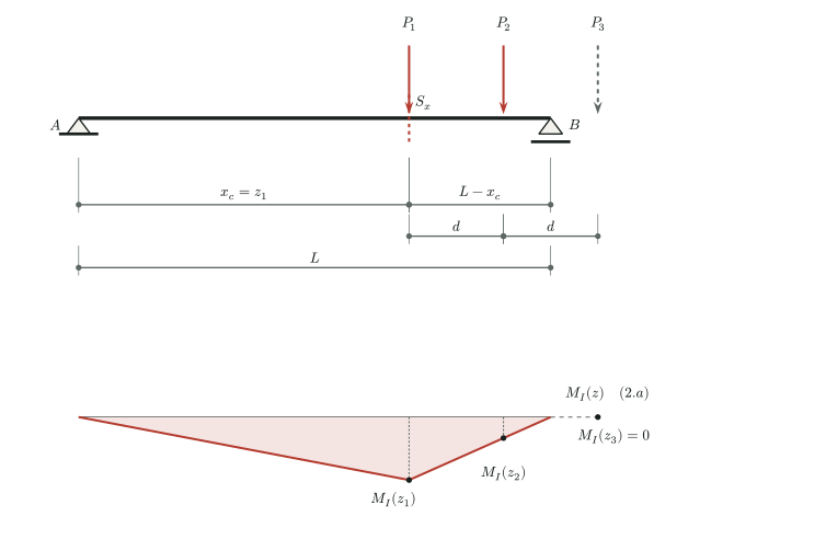
In this case:
\[\begin{equation} z_1(s) = s = x_c, \quad z_2(s) = s + d = x_c + d, \quad z_3(s) = s + 2d = x_c + 2d > L \end{equation}\]
Because load \(P_3\) is outside the beam, its influence-line ordinate is zero (that is, \(M_I^{(2.a)}(z_3) = 0\)), so its contribution to the bending moment at section \(x_c\) is also zero. The influence-line ordinates at the load positions are therefore:
\[\begin{equation} \begin{aligned} M_I^{(2.a)}(z_1) &= M_I^{(1.a)}(z_1) = \dfrac{z_1(L-x_c)}{L} = \dfrac{x_c(L-x_c)}{L}, \\ M_I^{(2.a)}(z_2) &= \dfrac{x_c(L-z_2)}{L} = \dfrac{x_c[L-(x_c+d)]}{L},\\ M_I^{(2.a)}(z_3) &= 0 \end{aligned} \end{equation}\]
Hence:
\[\begin{equation} \begin{aligned} M^{(2.a)}_{S_x} &= P_m [ M_I^{(2.a)}(z_1) + M_I^{(2.a)}(z_2) + M_I^{(2.a)}(z_3) ]\\ &= \dfrac{P_m x_c}{L} \{ [L-(x_c)] + [L-(x_c+d)] + 0 \}\\ &= \dfrac{P_m x_c}{L}(2L-2x_c-d) \end{aligned} \end{equation}\]
3.2 Case 2.b – Load \(P_2\) coincides with the section, with \(P_1\) on the span
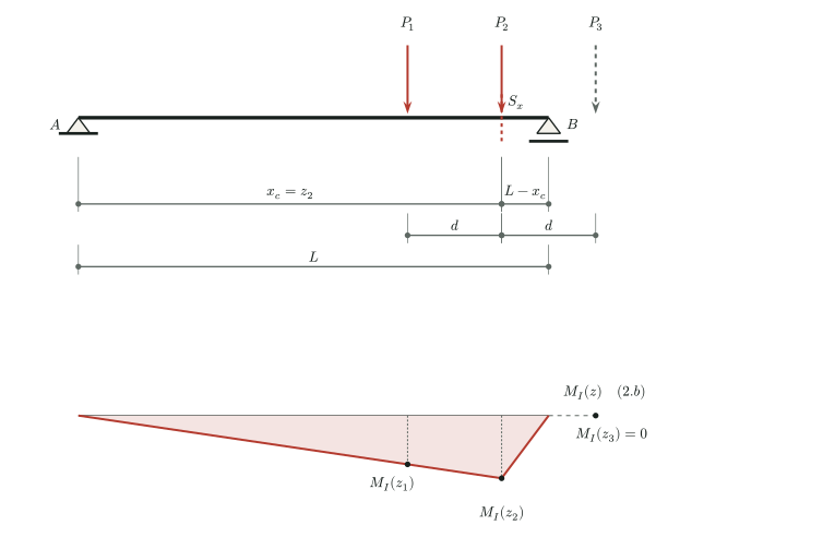
Here, \(z_1=x_c-d\), \(z_2=x_c\), and \(z_3=x_c+d>L\). The two loads acting on the beam occupy the same positions relative to the section as the loads in Case 2.c; because their magnitudes are equal, the moment is \(M^{(2.b)}_{S_x}=M^{(2.c)}_{S_x}=P_m(L-x_c)(2x_c-d)/L\), without repeating the derivation.
3.3 Case 2.c – The position \(z_3\) of load \(P_3\) coincides with the section position \(x_c\)
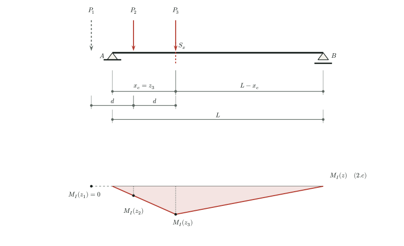
In this case:
\[\begin{equation} s=x_c-2d,\quad z_1(s)=s=x_c-2d<0,\quad z_2(s)=s+d=x_c-d,\quad z_3(s)=s+2d=x_c \end{equation}\]
Because load \(P_1\) is outside the beam, its influence-line ordinate is zero (that is, \(M_I^{(2.c)}(z_1) = 0\)), so its contribution to the bending moment at section \(x_c\) is also zero.
The influence-line ordinates at the load positions are therefore:
\[\begin{equation} \begin{aligned} M_I^{(2.c)}(z_1) &= 0, \\ M_I^{(2.c)}(z_2) &= \dfrac{z_2(L-x_c)}{L} = \dfrac{(x_c-d)(L-x_c)}{L},\\ M_I^{(2.c)}(z_3) &= M_I^{(1.c)}(z_3) = \dfrac{x_c(L-z_3)}{L} = \dfrac{x_c(L-x_c)}{L} \end{aligned} \end{equation}\]
Hence:
\[\begin{equation} \begin{aligned} M^{(2.c)}_{S_x} &= P_m [ M_I^{(2.c)}(z_1) + M_I^{(2.c)}(z_2) + M_I^{(2.c)}(z_3) ]\\ &= \dfrac{P_m}{L} \{ 0 + (x_c-d)(L-x_c) + x_c(L-x_c) \}\\ &= \dfrac{P_m(L-x_c)}{L}(2x_c-d) \end{aligned} \end{equation}\]
3.4 Case 2.d – Load \(P_2\) coincides with the section, with \(P_3\) on the span
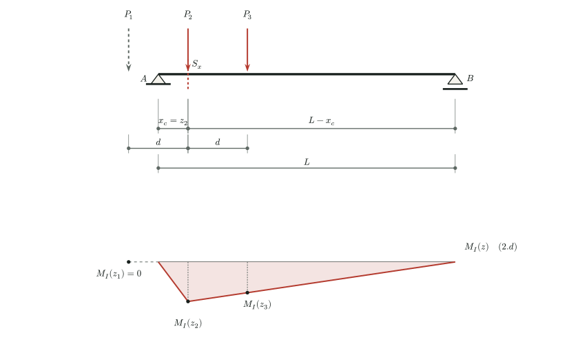
Here, \(z_1=x_c-d<0\), \(z_2=x_c\), and \(z_3=x_c+d\). The two loads acting on the beam occupy the same positions relative to the section as the loads in Case 2.a; therefore, \(M^{(2.d)}_{S_x}=M^{(2.a)}_{S_x}=P_m x_c(2L-2x_c-d)/L\).
4 Scenario 3 – All three loads are on the beam
In Scenario 3, all three loads are on the beam, that is, \(0 \le z_i(s) \le L\) for \(i \in \{1,2,3\}\). Three distinct cases must be considered, depending on the load positions relative to the fixed section \(S_x\):
Case 3.a – The position \(z_1\) of load \(P_1\) coincides with the position \(x_c\) of the fixed section, and the other loads are to its right;
Case 3.b – The position \(z_2\) of load \(P_2\) coincides with the position \(x_c\) of the fixed section, with one of the other loads to its left and the other to its right;
Case 3.c – The position \(z_3\) of load \(P_3\) coincides with the position \(x_c\) of the fixed section, and the other loads are to its left.
Individually, Case 3.a requires \(x_c+2d\le L\); Case 3.b requires \(d\le x_c\le L-d\); and Case 3.c requires \(x_c\ge 2d\). For all three cases to be feasible at the same section, \(2d\le x_c\le L-2d\) is required, implying \(L\ge4d\). This last condition is not needed for any one case to occur.
4.1 Case 3.a – The position \(z_1\) of load \(P_1\) coincides with the section position \(x_c\)
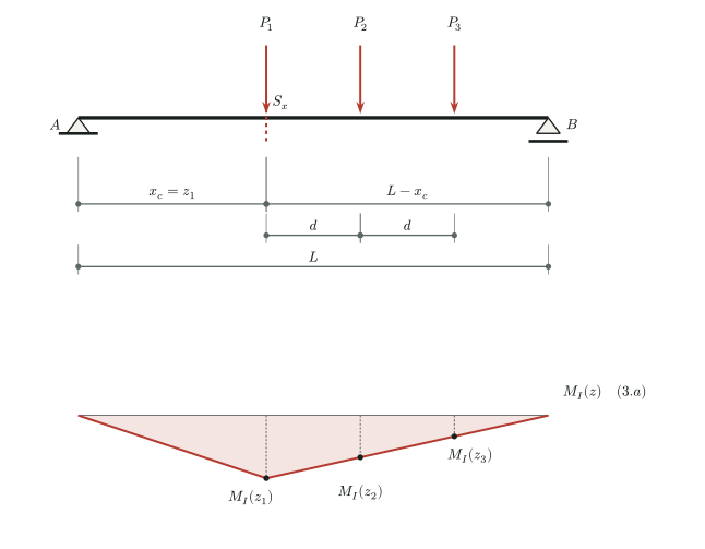
In this case:
\[\begin{equation} z_1(s) = s = x_c, \quad z_2(s) = s + d = x_c + d, \quad z_3(s) = s + 2d = x_c + 2d \end{equation}\]
The influence-line ordinates at the load positions are:
\[\begin{equation} \begin{aligned} M_I^{(3.a)}(z_1) &= M_I^{(2.a)}(z_1) = M_I^{(1.a)}(z_1) = \dfrac{x_c(L-z_1)}{L} = \dfrac{x_c(L-x_c)}{L}, \\ M_I^{(3.a)}(z_2) &= M_I^{(2.a)}(z_2) = \dfrac{x_c(L-z_2)}{L} = \dfrac{x_c[L-(x_c+d)]}{L},\\ M_I^{(3.a)}(z_3) &= \dfrac{x_c(L-z_3)}{L} = \dfrac{x_c[L-(x_c+2d)]}{L} \end{aligned} \end{equation}\]
Hence:
\[\begin{equation} \begin{aligned} M^{(3.a)}_{S_x} &= P_m [ M_I^{(3.a)}(z_1) + M_I^{(3.a)}(z_2) + M_I^{(3.a)}(z_3)]\\ &= \dfrac{P_m x_c}{L} \{ (L-x_c) + [L-(x_c+d)] + [L-(x_c+2d)] \}\\ &= \dfrac{3P_m x_c}{L}(L-x_c-d) \end{aligned} \end{equation}\]
4.2 Case 3.b – The position \(z_2\) of load \(P_2\) coincides with the section position \(x_c\)
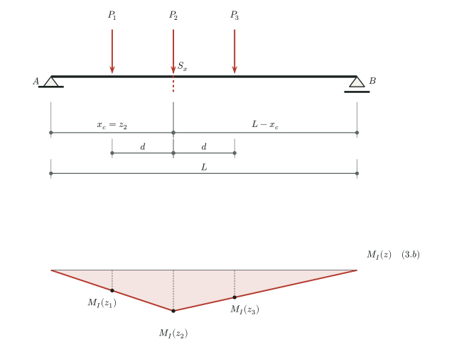
In this case:
\[\begin{equation} s=x_c-d,\quad z_1(s)=s=x_c-d,\quad z_2(s)=s+d=x_c,\quad z_3(s)=s+2d=x_c+d \end{equation}\]
The influence-line ordinates at the load positions are:
\[\begin{equation} \begin{aligned} M_I^{(3.b)}(z_1) &= \dfrac{z_1(L-x_c)}{L} = \dfrac{(x_c-d)(L-x_c)}{L}, \\ M_I^{(3.b)}(z_2) &= \dfrac{x_c(L-z_2)}{L} = \dfrac{x_c(L-x_c)}{L},\\ M_I^{(3.b)}(z_3) &= \dfrac{x_c(L-z_3)}{L} = \dfrac{x_c[L-(x_c+d)]}{L} \end{aligned} \end{equation}\]
Hence:
\[\begin{equation} \begin{aligned} M^{(3.b)}_{S_x} &= P_m [ M_I^{(3.b)}(z_1) + M_I^{(3.b)}(z_2) + M_I^{(3.b)}(z_3)]\\ &= \dfrac{P_m}{L} [ (x_c-d)(L-x_c) + x_c(L-x_c) + x_c[L-(x_c+d)] ]\\ &= \dfrac{P_m}{L} [ (x_c-d)(L-x_c) + x_c(L-x_c) + x_c(L-x_c) - x_c d] \\ &= \dfrac{P_m}{L} [ (3x_c-d)(L-x_c) - x_c d]\\ &= \dfrac{P_m}{L} [3x_c(L-x_c)-dL] \end{aligned} \end{equation}\]
4.3 Case 3.c – The position \(z_3\) of load \(P_3\) coincides with the section position \(x_c\)
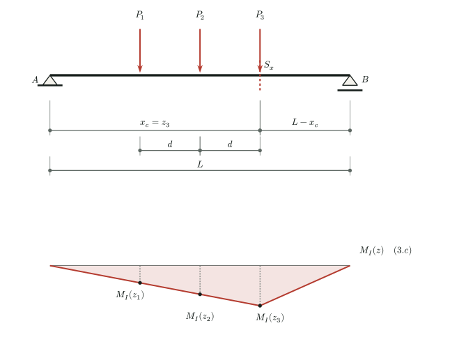
In this case:
\[\begin{equation} s=x_c-2d,\quad z_1(s)=s=x_c-2d,\quad z_2(s)=s+d=x_c-d,\quad z_3(s)=s+2d=x_c \end{equation}\]
The influence-line ordinates at the load positions are:
\[\begin{equation} \begin{aligned} M_I^{(3.c)}(z_1) &= \dfrac{z_1(L-x_c)}{L} = \dfrac{(x_c-2d)(L-x_c)}{L}, \\ M_I^{(3.c)}(z_2) &= M_I^{(2.c)}(z_2) = \dfrac{z_2(L-x_c)}{L} = \dfrac{(x_c-d)(L-x_c)}{L},\\ M_I^{(3.c)}(z_3) &= M_I^{(2.c)}(z_3) = M_I^{(1.c)}(z_3) = \dfrac{x_c(L-z_3)}{L} = \dfrac{x_c(L-x_c)}{L} \end{aligned} \end{equation}\]
Hence:
\[\begin{equation} \begin{aligned} M^{(3.c)}_{S_x} &= P_m [ M_I^{(3.c)}(z_1) + M_I^{(3.c)}(z_2) + M_I^{(3.c)}(z_3) ]\\ &= \dfrac{P_m(L-x_c)}{L} [(x_c-2d)+(x_c-d)+x_c]\\ &= \dfrac{3P_m(L-x_c)}{L}(x_c-d) \end{aligned} \end{equation}\]
5 Selecting the maximum bending moment at the fixed section
Over the vehicle’s entire passage, the reference position ranges from \(-2d\) to \(L\). The three candidate positions are \(s=x_c\), \(s=x_c-d\), and \(s=x_c-2d\). Using the influence line extended by zero beyond the span, define:
\[\begin{equation} \begin{aligned} M_a &= P_m[M_I(x_c)+M_I(x_c+d)+M_I(x_c+2d)],\\ M_b &= P_m[M_I(x_c-d)+M_I(x_c)+M_I(x_c+d)],\\ M_c &= P_m[M_I(x_c-2d)+M_I(x_c-d)+M_I(x_c)]. \end{aligned} \end{equation}\]
The result is:
\[\begin{equation} \boxed{M_{\max}(x_c)=\max\{M_a,M_b,M_c\}.} \end{equation}\]
These expressions also cover cases where \(P_2\) is at the section and only one or neither of its neighboring loads is on the beam. Thus, there is no need to require \(L\ge4d\) or to exclude the vehicle’s entry and exit phases. At case boundaries, a load directly on a support is still within \([0,L]\), but its influence-line ordinate is zero. For unequal loads or spacings, use the same weighted sum at the candidate positions \(s=x_c\), \(s=x_c-d_{1,2}\), and \(s=x_c-d_{1,2}-d_{2,3}\).
For example, with \(L=20\,\mathrm{m}\), \(x_c=8\,\mathrm{m}\), \(d=4\,\mathrm{m}\), and \(P_m=100\,\mathrm{kN}\), we obtain \(M_a=960\,\mathrm{kN\,m}\), \(M_b=1040\,\mathrm{kN\,m}\), and \(M_c=720\,\mathrm{kN\,m}\). Therefore, \(M_{\max}(8\,\mathrm{m})=1040\,\mathrm{kN\,m}\), with \(P_2\) directly over the section and \(s=4\,\mathrm{m}\).
At a support section, \(x_c=0\) or \(x_c=L\), all influence-line ordinates are zero, so the maximum moment is zero. The section remains fixed throughout the analysis: this article does not seek the absolute maximum over all sections of the beam.