
This article provides an introduction to structural analysis, covering its objectives, methodologies, and the types of responses and actions considered. It discusses computational modeling, distinguishing between the real structure and the idealized model used in the analysis. It also presents the different types of structural elements and structural systems. Emphasis is placed on framed structures (structures composed of columns, beams, and members in general, such as trusses, frames, and beam grids). Finally, it introduces the main beam theories: Euler–Bernoulli beam theory and Timoshenko beam theory.
1 Objective of Structural Analysis
Structural analysis aims to determine the responses (results) of a structure to the actions to which it is subjected. These responses provide an understanding of its behavior and information for safety and performance checks.
The responses most commonly of interest in structural analysis are:
support reactions (forces and moments);
internal forces and moments (axial force, shear force, bending moment, and twisting moment);
normal and shear stresses;
translational displacements and rotations;
normal and shear strains.
The actions most commonly considered in structural analysis arise from loads such as the structure’s self-weight, imposed loads, and wind forces. Actions may also involve temperature changes, concrete shrinkage, support settlements, and ground motions such as those caused by earthquakes.
In broad terms, this objective—determining a structure’s responses to a set of actions—can be achieved through two general approaches:
the empirical approach of experimental analysis;
the rational approach of theoretical analysis.
In experimental analysis, responses are measured on the actual structure or on a physical model in a laboratory. Strain gauges, displacement transducers, load cells, and accelerometers are examples of instruments used to measure strains, displacements, forces, and accelerations. The results can also be used to assess and calibrate theoretical models.
In theoretical analysis, equations are formulated and solved to represent approximately the behavior of a structural model. In general, theoretical methods can be classified as analytical or numerical.
In analytical methods, the governing equations are established on the basis of simplifying assumptions and solved analytically, yielding exact closed-form solutions (that is, without approximations in the solution). However, although an analytical solution is considered exact, it is actually the exact solution of a mathematical problem that represents the real problem approximately. In structural analysis, only very simple problems (with simple geometry, loading, and support conditions) can be solved analytically. Analytical solutions are expressed symbolically.
In numerical methods, the governing equations are established on the basis of simplifying assumptions that are usually more realistic than those adopted in analytical methods, and these equations are solved approximately with the aid of a computer. Numerical solutions are expressed as numbers.
This article focuses more specifically on theoretical structural analysis.
2 Structural Modeling
It is important to emphasize that, although the expression “analysis of a structure” is used, theoretical structural analysis actually examines a mathematical idealization of the real structure. Rather than analyzing a structure exactly as it exists or will exist in reality, a simplified model is analyzed. This model is created using simplifying assumptions intended to reduce the complexity of the real problem and is generally called a structural model. For example, Figure 1 shows the actual railway bridge over the Mearim River on the Carajás Railway. Figure 2 shows the structural model of the bridge used in computational structural analysis. The comparison illustrates how the real structure is represented by idealizing its geometry, connections, and support conditions.

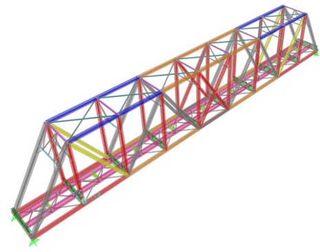
Creating the model is one of the most important stages of analysis. A single structure may require different models: for example, one to assess its overall behavior and another to study stresses in a connection. A more detailed model is not automatically better; it must suit the results sought and the available data.
Frequently adopted idealizations include:
Ideal geometry without imperfections – perfectly straight lines, plane faces, vertical members without out-of-plumbness, constant cross sections, and similar assumptions;
Homogeneous material – a material with the same properties at different points in space;
Isotropic material – a material with the same properties in different directions;
Linear elastic material – a material obeying Hooke’s law, with stresses proportional to strains, no strength limit, and no residual strains after unloading. This model does not describe yielding, cracking, or failure and must be used within its domain of validity;
Simplified loading – uniformly distributed loads, perfectly trapezoidal loads, concentrated loads, loads that do not vary with time, and similar assumptions;
Idealized support conditions – perfect restraints on specified displacements and rotations, according to the support type (for example, ideal roller, pinned, or fixed supports, without settlement);
Idealized connections – joints treated as perfectly pinned or rigid, as in conventional truss and frame models, respectively.
Given the many possible simplifying assumptions, the quality of the structural model depends greatly on the knowledge and experience of the engineer carrying out the analysis, as well as on the availability and quality of the problem data. When analysis is performed using a computer program, however, the realism of the model is also limited by the program’s capabilities. For example, if the program is restricted to the analysis of structures with linear elastic behavior, material strength cannot be taken into account within that analysis.
3 Common Types of Structural Elements
Structures are generally made up of smaller parts known as structural elements.
Although all real structural elements are three-dimensional, their representation can be classified according to their predominant dimensions and the behavior to be studied:
One-dimensional or line elements – these elements have one dimension that predominates over the other two. In other words, their length is much greater than the two cross-sectional dimensions. They are also commonly called member elements. Examples include beams, columns, and piles. Their axes may be straight or curved, as in beams curved in a horizontal plane and arch members in a vertical plane;
Two-dimensional or surface elements – these elements have two dimensions that predominate over the third. Their thickness is much smaller than their other two dimensions. Examples include slabs or plates, membranes, and shells. These elements may be flat or curved in space;
Three-dimensional or volume elements – these elements generally have no predominant dimension and have a more solid form. Examples include foundation blocks and blocks of gravity dams.
4 Common Types of Structural Systems
Combining one or more types of structural elements produces structural systems in various categories. Some of the most common are:
Framed or reticulated structures – structures formed by one-dimensional structural elements (line or member elements) connected at nodal points or joints. The members may be arranged along an axis, in a plane, or in space, forming, respectively, one-dimensional structures (such as continuous beams), two-dimensional structures (such as plane trusses and frames, and beam grids), and three-dimensional structures (such as space trusses and frames);
Surface structures – structures formed by surface elements connected along common edges. Examples include storage structures (water reservoirs, swimming pools, tanks, and silos) and shell roofs;
Volume or solid structures – structures formed by volume elements connected along common faces. Examples include gravity dams and pile caps.
It is common to combine structural systems involving different types of elements within one model. A typical example is a reinforced-concrete building, in which member elements represent beams, columns, and piles; plate or shell elements represent slabs and structural walls; and volume elements represent foundation blocks or the soil itself.
5 Types of Reticulated Structures
Reticulated structural systems are of great interest because they can represent an enormous variety of structures. This article therefore focuses on this type of structural system. The main types are:
Single-span or continuous beam – this system consists of member elements arranged along a single axis. Each member element usually represents a span. Loading is generally assumed to act in the plane of the structure, in which case the internal actions in the beam sections are axial force, shear force, and bending moment. In beam analysis, loads parallel to the beam axis, which produce axial force, are often omitted;
Plane frame – this system consists of member elements arranged in a plane and rigidly connected at nodal points. The members represent columns (vertical members) and beams (horizontal or inclined members). Loading is generally assumed to act in the plane of the structure, in which case the internal actions in the members are axial force, shear force, and bending moment;
Plane truss – this system consists of member elements arranged in a plane and connected at perfectly pinned joints. Because the joints are assumed to be perfectly pinned, the members must form triangular arrangements for the structure to be stable. Stability also depends on geometry, connectivity, and support restraints. Loads are assumed to act in the plane of the structure and only at the joints (so the self-weight of the members cannot be considered directly as acting along their lengths). Under these assumptions, the truss members carry axial force only. This system is commonly used to represent steel or timber roof structures and is also widely used in long-span steel bridges;
Beam grid – this system consists of member elements arranged in a plane and rigidly connected at nodal points. The members represent horizontal beams. Loading is generally assumed to act perpendicular to the plane of the structure, in which case the internal actions are shear force, bending moment, and twisting moment. This system is generally used to account for interaction between beams in the same horizontal plane, as in a typical building floor;
Space truss – this system consists of member elements arranged in space and connected at pinned joints. Because the joints are assumed to be perfectly pinned, stability requires the members to form stable arrangements such as tetrahedra or the edges of pyramids (extending the concept of the triangular arrangement of a plane truss to three dimensions). These are examples of configurations used, but stability must be checked for the entire system, including its connections and supports. Loads are assumed to be applied only at the joints (self-weight cannot be considered along the members). Under these assumptions, the truss members carry axial force only. This system is commonly used to represent long-span steel roof structures;
Space frame – this system consists of member elements arranged in space and usually rigidly connected at nodal points. The members represent columns (vertical members) and beams (horizontal or inclined members). In general, member sections are subjected to axial force, two shear-force components, a twisting moment, and two bending-moment components.
6 Beam Theories
The Euler–Bernoulli theory is commonly adopted for the analysis of framed structures. It is based on the simplifying assumption that member sections remain plane and perpendicular to the member axis after external actions (loading) are applied. With this assumption, shear strains are neglected when evaluating displacements. This does not mean that the shear force is zero.
The importance of shear deformation depends fundamentally on the ratio between, for example, a beam’s span and the depth of its cross section, in the case of a rectangular section.
Another, more recent and more accurate beam theory used for the analysis of framed structures is Timoshenko beam theory. It assumes that sections remain plane after deformation, but not necessarily perpendicular to the member axis, because of shear effects.
Timoshenko beam theory is more accurate than Euler–Bernoulli beam theory because it makes one fewer simplification: Euler–Bernoulli theory ignores shear strains. This simplification can cause considerable differences between the two theories for short beams (with a length-to-depth ratio below a value of approximately 2 or 3).
Some more sophisticated structural analysis programs, such as SAP2000, use Timoshenko beam theory to analyze structures composed of members. In SAP2000, however, Bernoulli beam theory can be imposed indirectly by setting shear strains to zero. This effect is obtained by assigning an infinite shear area to the cross section.
Both theories apply to member models and have limitations. Near supports, concentrated loads, or geometric discontinuities, and in short elements (with a small length-to-depth ratio), surface or volume models may be needed to study local effects.