
This note explains how to determine the maximum bending moment at a fixed section of a simply supported beam carrying three moving concentrated loads that represent a vehicle’s axles. The calculation uses the influence-line ordinates at the load positions. It accommodates different load magnitudes and spacings, as well as particular cases in which two loads or spacings are equal.
1 Bending moment for an arbitrary vehicle position
Consider a simply supported beam of span \(L\) subjected to three moving downward vertical concentrated loads, \(P_1\), \(P_2\), and \(P_3\), with positive fixed spacings \(d_{1,2}\) and \(d_{2,3}\), as illustrated in figure 1. The arrows are schematic and do not represent the relative load magnitudes. Let \(s\) be the reference position of the vehicle, and let the first load position coincide with it, so that \(z_1=s\). The other load positions follow from the fixed spacings.
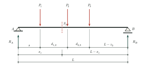
\[\begin{equation} z_1(s)=s,\qquad z_2(s)=s+d_{1,2},\qquad z_3(s)=s+d_{1,2}+d_{2,3} \end{equation}\]
Define the total spacing between the first and third loads as \(d_{1,3}=d_{1,2}+d_{2,3}\), so that:
\[\begin{equation} z_3(s)=s+d_{1,3}. \end{equation}\]
The bending-moment influence line at a fixed section \(S_x\) located at \(x_c\), for a unit vertical load at position \(z\), is defined below. A load outside the span, where \(z<0\) or \(z>L\), has a zero influence ordinate.
\[\begin{equation} M_I(z)= \begin{cases} \dfrac{z(L-x_c)}{L}, & 0\le z\le x_c,\\[5pt] \dfrac{x_c(L-z)}{L}, & x_c<z\le L,\\[5pt] 0, & z\notin[0,L]. \end{cases} \end{equation}\]
As shown previously, the bending moment at a fixed section is the sum of each load magnitude multiplied by the influence-line ordinate at that load’s position:
\[\begin{equation} M(s) = P_1 M_I\big(z_1(s)\big) + P_2 M_I\big(z_2(s)\big) + P_3 M_I\big(z_3(s)\big) \end{equation}\]
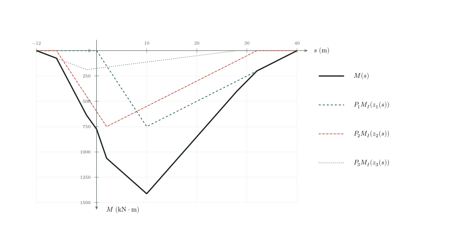
Figure 2 illustrates superposition for \(L=40\,\mathrm{m}\), \(x_c=10\,\mathrm{m}\), \(d_{1,2}=8\,\mathrm{m}\), \(d_{2,3}=4\,\mathrm{m}\), \(P_1=P_2=100\,\mathrm{kN}\), and \(P_3=25\,\mathrm{kN}\). The broken lines show the individual contributions \(P_j M_I(z_j(s))\), and the solid black line shows their sum \(M(s)\). At each abscissa \(s\), add the three ordinates for the same vehicle position, not the individual maxima of the curves. Each contribution is zero while its load is outside the span and peaks when that load passes over the fixed section, at \(s=10\), \(2\), and \(-2\,\mathrm{m}\), respectively. Positive moments are plotted downward, without changing the signs of the displayed values. The sum is piecewise linear and reaches \(1412.5\,\mathrm{kN\,m}\) at \(s=10\,\mathrm{m}\).
Thus, the bending moment at any fixed section can be determined for any vehicle position as the loads move along the span.
2 Maximum bending moment and critical vehicle positions
Determining the maximum bending moment requires identifying the critical load positions. For statically determinate structures, influence lines are piecewise linear functions, consisting of straight segments that form a polygonal function. Their sum is also piecewise linear, as figure 2 illustrates. Consequently, a maximum occurs at a position where a concentrated load coincides with a vertex of the influence line.
For the bending moment of a simply supported beam, the influence line has two linear branches within the span, is zero at the supports, and has a vertex at the fixed section \(x_c\). Loads outside the span produce no internal force, so the complete influence line can be represented by four branches: two within the span and two zero branches outside it. During the complete vehicle passage, at least one maximum therefore occurs when a load is exactly over the fixed section, that is, when \(z_i(s)=x_c\) for some \(i\in\{1,2,3\}\).
3 Cases with all three loads on the span
When all three loads are on the span, it is sufficient to evaluate the three candidate alignments in which one load coincides with the fixed section: \(z_1=x_c\), \(z_2=x_c\), or \(z_3=x_c\). These are called cases a, b, and c, respectively.
3.1 Case a — Load \(P_1\) coincides with the fixed section
In this case, \(P_1\) is directly over the fixed section (\(z_1=x_c\)). The other load positions are determined by the fixed spacings:
\[\begin{equation} z_1 = x_c, \quad z_2 = x_c + d_{1,2}, \quad z_3 = x_c + d_{1,3} \end{equation}\]
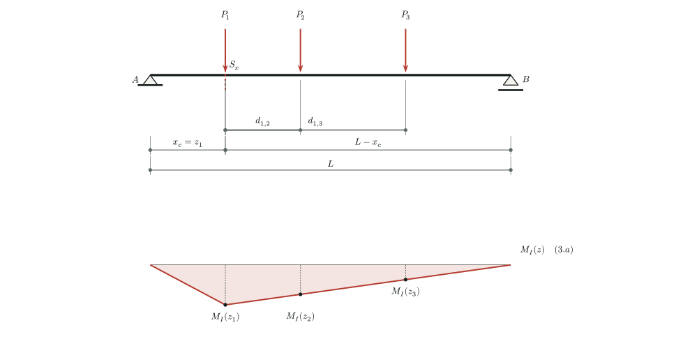
The bending moment in this case is:
\[\begin{equation} \begin{aligned} M_a(x_c) &= P_1 M_I(z_1) + P_2 M_I(z_2) + P_3 M_I(z_3)\\ &= P_1 M_I(x_c) + P_2 M_I(x_c + d_{1,2}) + P_3 M_I(x_c + d_{1,3}) \end{aligned} \end{equation}\]
3.2 Case b — Load \(P_2\) coincides with the fixed section
Here, \(P_2\) is directly over the fixed section (\(z_2=x_c\)). The other load positions are:
\[\begin{equation} z_1 = x_c - d_{1,2}, \quad z_2 = x_c, \quad z_3 = x_c + d_{2,3} \end{equation}\]
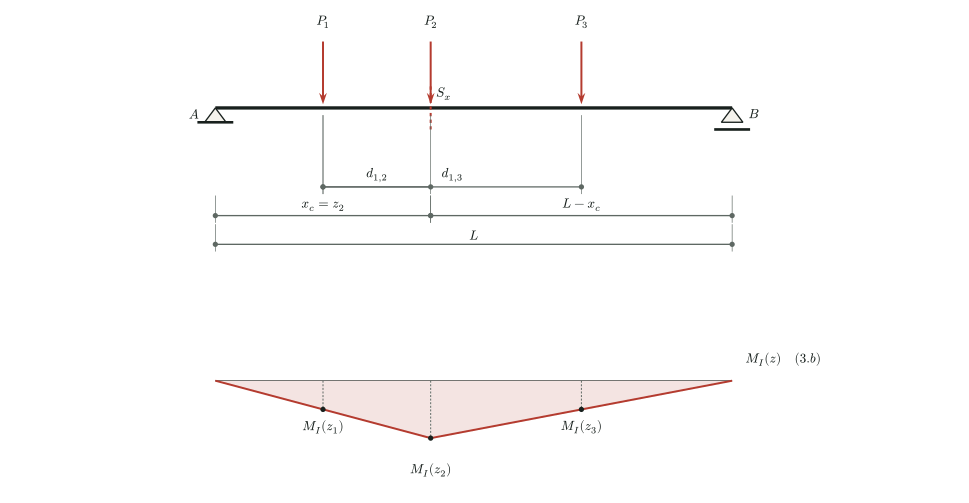
The bending moment in this case is:
\[\begin{equation} \begin{aligned} M_b(x_c) &= P_1 M_I(z_1) + P_2 M_I(z_2) + P_3 M_I(z_3)\\ &= P_1 M_I(x_c - d_{1,2}) + P_2 M_I(x_c) + P_3 M_I(x_c + d_{2,3}) \end{aligned} \end{equation}\]
3.3 Case c — Load \(P_3\) coincides with the fixed section
Here, \(P_3\) is directly over the fixed section (\(z_3=x_c\)). The other load positions are:
\[\begin{equation} z_1 = x_c - d_{1,3}, \quad z_2 = x_c - d_{2,3}, \quad z_3 = x_c \end{equation}\]
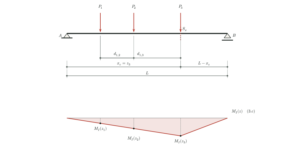
The bending moment in this case is:
\[\begin{equation} \begin{aligned} M_c(x_c) &= P_1 M_I(z_1) + P_2 M_I(z_2) + P_3 M_I(z_3)\\ &= P_1 M_I(x_c - d_{1,3}) + P_2 M_I(x_c - d_{2,3}) + P_3 M_I(x_c) \end{aligned} \end{equation}\]
4 Critical positions with one or more loads outside the span
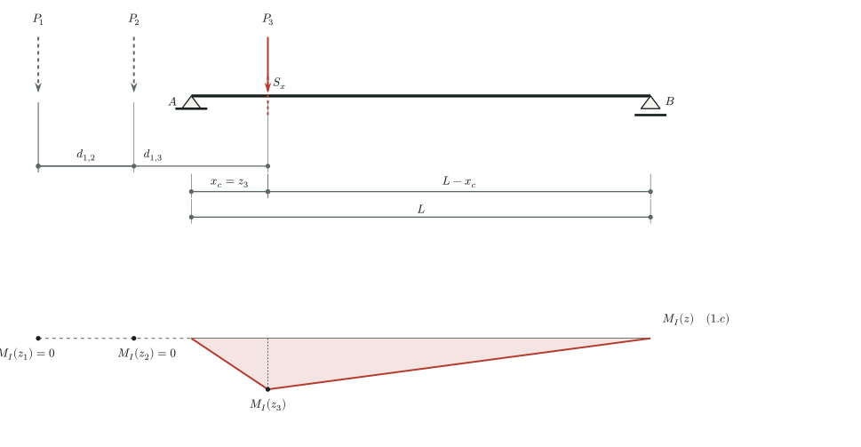
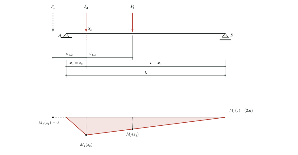
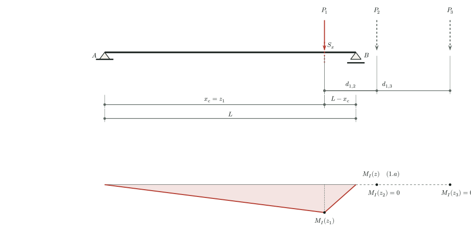
The same candidate alignments apply when one or more loads are outside the beam. At those positions, \(M_I(z_j)=0\), so the corresponding load contributes nothing to the section moment. The following figures illustrate configurations with only \(P_3\) on the span, with \(P_2\) and \(P_3\) on the span, and with only \(P_1\) on the span. They illustrate the general method and do not require separate equations.
5 General determination of the maximum
The maximum bending moment at a fixed section is found by evaluating the three load-at-section candidates:
\[\begin{equation} \begin{aligned} M_a(x_c)&=P_1M_I(x_c)+P_2M_I(x_c+d_{1,2})+P_3M_I(x_c+d_{1,3}),\\ M_b(x_c)&=P_1M_I(x_c-d_{1,2})+P_2M_I(x_c)+P_3M_I(x_c+d_{2,3}),\\ M_c(x_c)&=P_1M_I(x_c-d_{1,3})+P_2M_I(x_c-d_{2,3})+P_3M_I(x_c). \end{aligned} \end{equation}\]
The maximum is:
\[\begin{equation} \boxed{M_{\max}(x_c)=\max\{M_a(x_c),M_b(x_c),M_c(x_c)\}.} \end{equation}\]
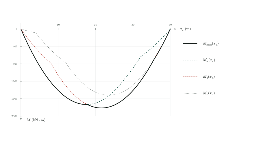
Figure 9 shows \(M_a(x_c)\) as a dashed line, \(M_b(x_c)\) as a dash-dot line, \(M_c(x_c)\) as a dotted line, and \(M_{\max}(x_c)\) as a thick solid black line, using the same span, loads, and spacings as the preceding example. At each position \(x_c\), select the largest of the three ordinates, not their sum. Since positive moments are plotted downward, the maximum envelope is the curve farthest from the horizontal axis. Unlike the superposition plot against \(s\), this figure varies the section position: each abscissa represents an independent analysis of the complete vehicle passage at a fixed section. The candidate functions are piecewise quadratic, changing expression when a load enters or leaves the span.
The influence-line ordinates are evaluated at each candidate position, including when one or two loads are outside the span. The same weighted sum therefore covers all the illustrated configurations without additional case-specific equations. A general numerical implementation only needs to evaluate the three weighted sums and select the largest value.
For example, let \(L=40\,\mathrm{m}\), \(x_c=10\,\mathrm{m}\), \(d_{1,2}=8\,\mathrm{m}\), \(d_{2,3}=4\,\mathrm{m}\), \(P_1=P_2=100\,\mathrm{kN}\), and \(P_3=25\,\mathrm{kN}\). The candidates are \(M_a=1412.5\,\mathrm{kN\,m}\), \(M_b=1062.5\,\mathrm{kN\,m}\), and \(M_c=637.5\,\mathrm{kN\,m}\). Thus, \(M_{\max}(10\,\mathrm{m})=1412.5\,\mathrm{kN\,m}\), with \(P_1\) over the section and \(s=10\,\mathrm{m}\).
At a support section, \(x_c=0\) or \(x_c=L\), all influence ordinates are zero and the maximum bending moment is zero. The section remains fixed throughout this analysis; this note does not seek the absolute maximum over all sections of the beam.