
1
Structural model
Consider the structural model of a simply supported beam with span \(L\), supported at points \(A\) and \(B\), and subjected to a uniformly distributed vertical load of intensity \(q\) over the entire span. The load resultant is \(qL\) and acts at midspan. The desired results are the support reactions \(R_A\) and \(R_B\), and the internal actions (shear force or bending moment) at a given section \(S_x\) of the beam.
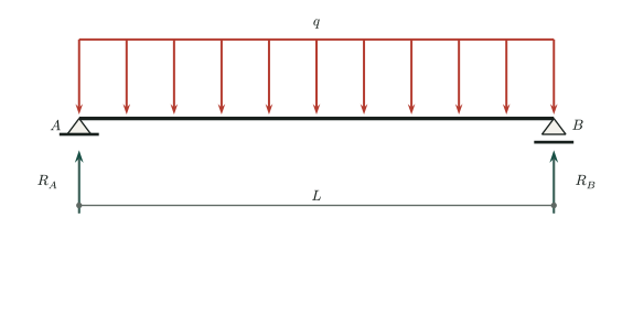
- \(L\)
- Beam span
- \(q\)
- Downward load per unit length
- \(R_A,R_B\)
- Upward support reactions
- \(S_x\)
- Variable position of a section \(S_x\)
2
Support reactions
To determine the support reactions, the distributed load can be replaced by its resultant \(qL\), applied at the load's centroid, which in this case is exactly at midspan. Vertical-force equilibrium and moment equilibrium about a point can then be imposed (point \(A\) is chosen here). Applying these equilibrium conditions yields the support reactions \(R_A\) and \(R_B\):
The reactions are equal because the loading and supports are symmetric.
3
Internal forces
The beam can be imagined as cut at a cross section \(S_x\) with coordinate \(x\), creating two free bodies, and the forces to the left or right of this cut can be examined. The figure separately shows the free-body diagrams of the left and right parts, including the distributed load on each part and the respective support reaction. For each free body to be in equilibrium, the internal actions acting on the cut faces must be considered: the shear force and bending moment.
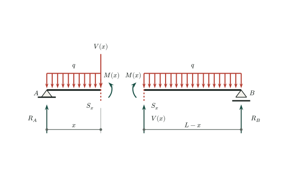
Positive shear acts downward on the cut face of the left free body and upward on the cut face of the right free body; bending moments that cause tension in the lower fibers are positive when they act counterclockwise on the cut face of the left part and clockwise on that of the right part. Thus, the two free bodies show internal actions at the cut section with equal magnitudes and opposite directions.
4
Shear force
On the left free body, the resultant of the partial load is \(qx\), applied at \(x/2\) from support \(A\). Vertical-force equilibrium of the left free body gives the shear force at the cut.
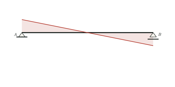
The shear force is a continuous linear function of \(x\); in other words, it varies linearly along the beam. Thus, the shear-force diagram is a straight line from \(+qL/2\) at \(A\) to \(-qL/2\) at \(B\), with a value of zero exactly at midspan.
5
Bending moment
Taking moments of the forces on the left free body about the cut gives the bending moment.
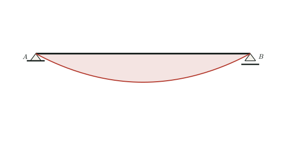
The bending moment is a continuous quadratic function of \(x\); in other words, it varies quadratically along the beam. Thus, the bending-moment diagram is a symmetric parabola, positive between the supports and with its maximum value at midspan.
6
Checks and limitations
- The reaction sum satisfies \(R_A+R_B=qL\).
- The shear changes by \(-qL\) from the left support to the right support.
- The bending moment vanishes at both simple supports and is maximum where the shear is zero.
These equations are valid only for a simply supported beam with a constant load intensity acting over the entire span.