
1
Structural model
Consider the structural model of a simply supported beam of span \(L\) connecting points \(A\) and \(B\). Point \(A\) is a fixed support (second-order support) and point \(B\) is a simple sliding support (first-order support). A concentrated gravitational load of magnitude \(P\) is located at a point with coordinate \(z\), measured from \(A\). The desired results are the support reactions \(R_A\) or \(R_B\), or an internal force (shear force or bending moment) at a given section \(S_x\) of the beam.
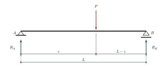
- \(L\)
- Beam span
- \(z\)
- Variable load position
- \(P\)
- Load magnitude (downward)
- \(R_A, R_B\)
- Upward support reactions
2
Support reactions
Vertical equilibrium and moment equilibrium about \(A\) give
Therefore, the support reactions are linear functions in \(z\):
- \(R_A(z)\)
- Left support reaction due to a load of magnitude \(P\) at position \(z\)
- \(R_B(z)\)
- Right support reaction due to a load of magnitude \(P\) at position \(z\)
The identity \(R_A(z)+R_B(z)=P\) is a useful equilibrium check for every load position.
3
Influence lines
Mathematically speaking, an influence line is a graph representing a function of the form \(y=f(z)\) for a point (or section) of the structure, where the independent variable (abscissa) is the position \(z\) of a moving unit load, and the ordinate \(y\) corresponds to the value of a desired response, such as a support reaction or an internal force (shear force or bending moment).
In other words, at each load position \(z\), the influence-line ordinate is the selected response caused by a load of magnitude one. Reaction and shear influence line ordinates are dimensionless; moment influence line ordinates have units of length.
4
Support-reaction influence lines
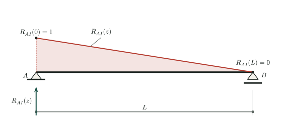
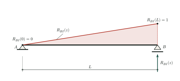
Setting \(P=1\) gives the support-reaction influence lines, which are linear in \(z\):
- \(R_{AI}(z)\)
- Function for left support reaction influence line
- \(R_{BI}(z)\)
- Function for right support reaction influence line
5
Internal forces
Imagine cutting the beam at a cross-section \(S_x\) with coordinate \(x\), creating two free bodies, and examine the forces to the left or right of the cut. Shear force \(V\) is defined as the algebraic sum of external vertical forces acting on the chosen free body (to the left or right of the section). Bending moment \(M\) is defined as the algebraic sum of the moments about section \(S_x\) of all external forces acting on the chosen free body. The expression used to compute the internal forces depends on whether the section is to the left or right of the moving load. This gives two cases:
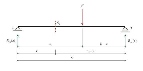
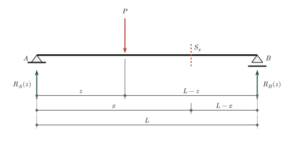
- \(x\)
- Variable position of a section \(S_x\)
6
Shear force
The shear force \(V\) acting at a section \(S_x\) is defined as the sum of all transverse forces (in this case, vertical forces) acting on one particular side of that section \(S_x\). A sign convention is used whereby vertical forces acting to the left of the section are positive when directed upward and negative when directed downward. For vertical forces acting to the right of the section, the sign convention is reversed.
In the context of a beam subjected to a single vertical load \(P\), the shear force at a section \(S_x\), located at \(x\), due to a load \(P\) at \(z\), is represented as \(V(x,z)\), that is, as a function of two variables, \(x\) and \(z\).
- \(V(x,z)\)
- Shear force at section \(S_x\), located at \(x\), due to a load \(P\) at \(z\)
Case 1: the section cut \(S_x\) is located to the left of the load \(P\). In this case, \(x\lt z\).
The left free body contains only the left reaction:
Case 2: the section cut \(S_x\) is located to the right of the load \(P\). In this case, \(x\gt z\).
The left free body contains both \(R_A\) and the downward load \(P\):
Combining the two equations above gives the shear force at section \(S_x\) due to a load \(P\) at \(z\):
7
Shear force diagram
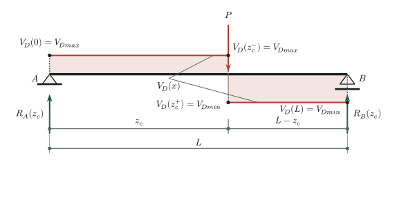
For the shear force diagram, the load magnitude \(P\) is kept general and the load position is fixed at a constant value \(z=z_c\). The shear force diagram is then a function of the section position \(x\) only, defined as \(V_D(x)=V(x,z_c)\). The section is to the left of the load when \(x\lt z_c\) and to the right when \(x\gt z_c\), so the result above gives:
The shear force is constant on each side of the load and drops by \(P\) at \(x=z_c\), where the load is applied: \(V_D(z_c^+)-V_D(z_c^-)=-P\). The diagram is plotted below for a load at \(z=z_c\).
8
Shear force influence line
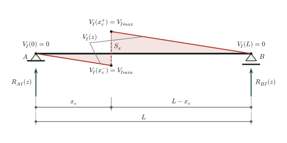
To obtain the shear force influence line, set \(P=1\) and fix the section position at a constant value \(x=x_c\). The influence line is then a function of the load position \(z\) only, defined as \(V_I(z)=V(x_c,z)\). From the result above:
At the section, shear has two one-sided values: the minimum ordinate \(V_{ILmin}\), when the section is immediately to the right of the load (\(x_c^-=z\)), and the maximum ordinate \(V_{ILmax}\), when the section is immediately to the left of the load (\(x_c^+=z\)):
The unit discontinuity occurs because the moving unit load enters or leaves the free body exactly at \(x\). The calculator therefore reports both limits instead of assigning one arbitrary shear ordinate at the discontinuity.
9
Bending moment
The bending moment \(M\) acting at a section \(S_x\) is defined as the algebraic sum of the moments about that section of all external forces acting on one particular side of the section. A sign convention is used whereby sagging moments are positive and hogging moments are negative.
In the context of a beam subjected to a single vertical load \(P\), the bending moment at a section \(S_x\), located at \(x\), due to a load \(P\) at \(z\), is represented as \(M(x,z)\), that is, as a function of two variables, \(x\) and \(z\).
- \(M(x,z)\)
- Bending moment at section \(S_x\), located at \(x\), due to a load \(P\) at \(z\)
Case 1: the section cut \(S_x\) is located to the left of the load \(P\). In this case, \(x\lt z\).
The load \(P\) is absent from the left free body, so
Case 2: the section cut \(S_x\) is located to the right of the load \(P\). In this case, \(x\gt z\).
Taking moments of the left-side forces about the cut gives
Combining the last two equations above gives the bending moment at section \(S_x\) due to a load \(P\) at \(z\):
10
Bending moment diagram
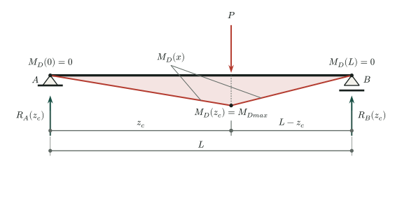
For the bending moment diagram, the load magnitude \(P\) is kept general and the load position is fixed at a constant value \(z=z_c\). The diagram is then a function of the section position \(x\) only, defined as \(M_D(x)=M(x,z_c)\). The section is to the left of the load when \(x\le z_c\) and to the right when \(x\ge z_c\), so the result above gives:
The diagram is continuous and piecewise linear, and its slope is the shear force \(V_D(x)\). The maximum bending moment occurs under the load:
11
Bending-moment influence line
To obtain the bending moment influence line, set \(P=1\) and fix the section position at a constant value \(x=x_c\). The influence line is then a function of the load position \(z\) only, defined as \(M_I(z)=M(x_c,z)\). From the result above:
Unlike shear, moment is continuous at the section. Both branches produce the same peak ordinate:
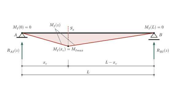
12
Checks and limitations
- At \(z=0\): \(R_A(z)=R_A(0)=P\), \(R_B(z)=R_B(0)=0\) and \(M(x,z)=M(x,0)=0\).
- At \(z=L\): \(R_A(z)=R_A(L)=0\), \(R_B(z)=R_B(L)=P\) and \(M(x,z)=M(x,L)=0\).
- The shear jump at \(z=x\) is exactly the load magnitude \(P\) (equal to 1 for the influence line), and so is the drop of the shear force diagram at \(x=z_c\).
- Reaction and shear influence line ordinates are dimensionless; moment influence line ordinates have units of length. The moment influence-line ordinate \(M_I(z)\) has units of length because it corresponds to the product of a dimensionless unit force and a distance (length), whereas the ordinates of \(M_D(x)\) have units of force times length.
These expressions assume a linear, statically determinate, single-span simply supported beam and a concentrated load. Overhangs, internal hinges, distributed moving loads, and indeterminate systems require additional formulations.